 |
|---|
WILTON MAK
ABAQUS Program
This project focused on the influence of angle of attack in response to airflow in free stream. The airfoil was simulated on ABAQUS CAE using an existing airfoil coordinates for a commercial airliner, Boeing 737. The midspan was extruded to provide analysis of differential length of the wing. ABAQUS meshed the airfoil into finite elements, and simulations produced 8-node analyses for the behavior of the midspan differential length at various angles of attack.
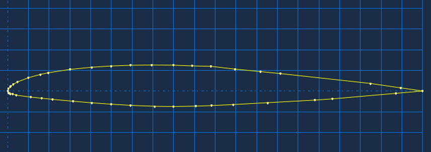
In the creating the airfoil model, a three dimensional extrusion was created. The coordinates of the midspan were found on Airfoil Tools and placed into ABAQUS as a sketch, as seen above.
In this analysis, the depth used in ABAQUS represented the dx, the differential form, of the midspan. Thus, this property represented an infinitesimally small portion of the wing. The following illustrations display with midspan airfoil with two different mesh sizes: 0.015 and 0.050. A mesh size of 0.050 was able to model the airfoil in drastically less time within 98% accuracy.


Carbon fiber constituted the airfoil model. The left end of the airfoil model was selected as the fixed end and represented the portion of the wing connected to the main body of the airliner. In creating a load for the model, surface traction was selected as the type of load. Vector loads were indicated to act upon the airfoil, and direction of the load simulated different angles of attack. Three loads were created: positive angle of attack, zero angle of attack, and negative angle of attack.
 Positive Angle of Attack |  PAA Deformed Shape |
|---|---|
 PAA Von Mises |  Zero Angle of Attack |
 ZAA Deformed Shape |  ZAA Von Mises |
 Negative Angle of Attack |  NAA Deformed Shape |
 NAA Von Mises |
The deformed shapes and von mises stress gradients at the various angles of attack were captured. These images were further used to generalize the manner in which the midspan airfoil respondsed to airflow.